According to Peter: This is hot rodding made easy. The M30 engine has the same basic block from 1972 to 1993. Virtually any big six will bolt right into the E12 engine bay. Some, particularly the '89-'93 blocks, require adaptation. When you get ready to buy your engine, post a message on www.firstfives.org so we can give you the particulars.
The L Jet and Motronic Injection systems are unitized so they can be transplanted easily from car to car. The entire process is strictly bolt up, there are no special brackets, no welding, no one off pieces. You can do this in California and still pass smog.
Why
a 3.5? The larger engine
makes the E12 A TRUE EUROPEAN AUTOBAHN cruiser.
The car just feels great. Its the engine that Gunther and Ugo always had
in mind for the E 12.
Grassroots
magazine has several great articles including performance results on their E12
with a 3.5. (Since sold)
According to Sean:
Faced with a pretty much perfect E12, original owner car, I had to decide if a 2.8
cylinder head (needed valve seals, but was still very strong), was worth the
$800 or so to replace (labor not included). It was consuming oil at the rate of
1 quart per fill-up. So was I to spend the $800 or should I go a bit extra
(turned into around $2500) and replace the motor with a 3.5ltr? I chose the
latter… A few reasons to go this route were evident: MORE Horsepower with the
same weight, Save the newer catalytic converter from being loaded up with oil, and MORE
Horsepower!
DunRite's Disease:
Sean
has this aversion to making sure things are DONE RIGHT! It may be a bit on the
anal side, but it proves to be effective in the long run. Hence: DUNRITE’s
disease…. Reminds me of an old advertisement: “you can pay me now….
OR you can pay me later”.
Our
directions include Mr. Dun-Rite editorials for perfectionists who have lots of
time.
OK
Now the FAQ’s:
L Jet vs Motronic
First
off, this covers converting from a 2.8 with L-Jet FI to a 3.5 using the same
L-Jet setup. Peter included a nice comparison chart for L-Jet vs. Motronic.
Motronic is a definite consideration and will surely add MORE Horsepower, but
also introduces a number of other items/considerations that need to be added to
the conversion. This will also drive the price up and time to build it out.
|
|
Consideration |
L-Jet
|
Motronic
|
|
|
Donor
Parts required |
Long
Block only Re
use injection system, flywheel, ECU and AFM. |
Long
Block, Manifolds, Wire Harness, AFM,
Computer, flywheel w/ timing devices, 1985(only) bell housing to mate to
your Gertrag 265, or automatic tranny with timing devices. 87’s
read off Harmonic balancer |
|
|
|
Other
Parts |
Reuse
engine mounts, AC, alt, PS brackets, pulleys, water pump, fan, Radiator,
thermostat housings. Reuse
E12 oil pan, use E28 damper |
Reuse
E12 AC, pulleys, water pump,
fan, , use E28 thermostat
housings, Reuse
E12 oil pan, E12 PS, E12 alt, use E 28 damper |
|
|
|
Relative
Labor |
Lots
more R & R from old engine to new 3.5 for the injection system. Majority
of the labor is in removal and replacement of engine. |
Have
to change over PS, alt brackets, engine mounts, oil pan Better
have all the Motronic pieces. |
|
|
|
Relative
Cost |
Dismantlers
– Long Block $1000 to $1500 depending on condition E
Bay, Local - $300 & up U
Pull It - $ 100 & up |
Dismantlers
– Long Block $1000 to $1500 depending on condition $100
– 300 computer $100
– 300 AFM $75
Flywheel $??
85 bellhousing Best
deal – wrecked car |
|
|
|
Tuning |
Have
to mess with mixture, idle, and possibly fuel pressure. (You
can mess w/ mixture, idle and pressure, and timing) |
Plug
and play 85
and later are “Chip-able” Avoid
83 & 84 w/ idle computer |
|
|
|
Performance |
Works
pretty well. Flat
spots at 4000 RPM. Need
320i intake runners for better Breathing.
Need 3.5 exhaust system for even better breathing. |
212
HP if from 85 or later car Manifold
is more highly tuned. Smoother
power delivery. |
|
|
|
Aesthetics |
Love
those long runners and that log
manifold ! Still
has that jet turbine whine from the AFM |
Less
hoses and US smog afterthoughts Seamless
power |
|
Finding an Engine & Components
There
are numerous avenues to your 3.5 (or 3.3 engine).
The
easiest (and most expensive)
Peter
went to a BMW dismantler, Double 02 Salvage for his engine.
They had 7 to choose from at the time. Sean
originally found an engine (long block with motronic intake) in Texas
from an 88 735i. The great thing about this particular engine is that it has the
triggering for a possible motronic install on the front Harmonic balancer. Turns
out this motor was damaged in the valve train and went back to the vendor. Sean
located a second engine, an 85 3.5 in CA. The
California dismantlers sell the complete engine less the transmission, AFM and
ECU. They will usually record the
pressure for each cylinder. PC got
one with 165psi in all 6 cylinders. Sean’s
were all above 160 psi. There are
numerous national dismantlers on the web.
The
best (and most challenging)
Find
a 535i, or better, a 735i wreck with an automatic and low freeway miles driven
by a little old lady whose son is a perfectionist BMW mechanic who changed the
oil every 1500 miles. Pay $1,500
for the miserable wreck, sell the seats, instruments, and wheels and voila!
A free engine. Even better would be an 87 to 92 model with the 212 hp engine
and “chipable” motronic.
If
you have the time
Surf
eBay relentlessly. Surf First Fives
relentlessly. Surf E28 Boards
relentlessly. Read the local Auto
Trader religiously. Make friends
with all the local insurance agents to see if they are totaling out any donor
BMW’s. Get friendly with your
local BMW dealer parts man. They
are a gossip center for BMW stuff.
Stay
away from
Advertised
rebuilders that note in the fine print that parts are replaced only where
required. Any engine over 150,000
miles. Any engine from a car fire.
Engine recently rebuilt by college dropout to pay for drug rehab.
Any engine advertised that needs work.
Once
you see one - what do you look at?
(We
need help here from the experts)
Pull
the sparkplugs. Are they all the same in appearance. Do the ceramic tips have a tan color.
Pull
the cam cover.
What is the general color and texture.
Golden glow. Even coating. No deposits.
(Slimy, gunky, dark brown, dark black are signs of poor oil maintenance)
Feel
the cam lobes.
With your trusty fingernail, scratch across the high part of a lobe,
especially number one cylinder. You
should not feel any ridges. If you
do the cam is shot.
Look
in the intakes
They should be spanky clean and free from oil.
The aluminum should gleam.
Look
at the exhausts Should
be an even dull flat black. No
white powder look. No oil.
All even.
Look
in the water ports They should be grunge
free. Light white deposits indicate
regularly changed antifreeze. There
should be no traces of oil.
Check
head gasket There
should be no oil oozing from it. Look
over starter area.
Check
oil pan
Leakage should be minimal. Check
residue at drain plug.
Overall
appearance The
engine should be relatively clean and free from tons of grunge.
If not keep looking. BMW’s
are being wrecked every day.
Make
sure your donor includes the following:
Harmonic Balancer & pulley set
Flywheel (if manual tranny)
Water pump and pulley (even though you’ll be replacing the pump).
A
majority of time will be pre prep. Getting ALL the needed gaskets, seals,
fluids, cleaning solutions, gloves, tools, parts, etc. in advance is the way to
go. You don’t want to be chasing down things while you are working. It wastes
A LOT of time! We can’t stress
the need to get all NEW gaskets/seals for the engine. Changing them while the
motor is out is easy and will save you considerable work after the motor is in (DunRite
raises his head here…). BWM doesn’t sell engine gasket/seal sets, so
you’ll need to get them individually. The list is long, but most all of the
gaskets are the same for all the years up to 88 (We think) for both the 2.8 and
the 3.5. They are the same block. The Mobile Traditions CD is VERY useful here.
It not only lists part #’s but also list bolt sizes and lengths.
(Sean is working on a parts listing)
Okay….
So now you’ve got all the goods, engine, gaskets, hoist, etc…. We used two
cement blocks under the front tires to get the car high enough to get under it.
It’s pretty stable, jack stands are also recommended as an additional safety
item. Chock the rear wheels. A lift would be nice, but hey….. a driveway works
too…
The
Ongoing Saga ..................
Sean
......
The
next thing I would tackle, and it is a bit disputed by Peter and others, is to
remove the transmission. In my case it’s a five speed. I won’t venture Auto
trans models here. If your hoist has a tilter cradle, then tranny removal may
not be required. Every engine swap I’ve done, I have removed the tranny first.
PC........
This
issue ended up being the most controversial issue of all during each of our
transplants. We will walk you
through the highlights of yanking that nasty engine out of that teeny space and
shoe horning it back in.
PC,
possessing greater in depth BMW experience than Sean… Thought he had the
engine removal scheme all figured out ! Not !
When
PC did his engine swap he decided to keep the tranny on the engine, disconnect
the driveline and pull the whole engine/tranny assembly out.
PC had a conventional engine hoist with chain bridging the water pump
bracket and the bellhousing point. The
car was jacked up on jack stands approximately 16” behind the front wheel
wells. He also had the rear on jackstands at 12”.
Even with engine at an extreme upward tilt it was a struggle to get the
tranny to clear the transmission hump at the firewall whilst keeping the pulleys
from decimating the AC Condenser. As
a result PC tore up the foil covered black rubber acoustics at the firewall.
For
Sean’s car, PC was convinced that
we should leave the tranny in place, undo the 4 – 19mm transmission bolts, and
pull the engine/bell-housing out. Enhancing
this wonderful labor saving method was the discovery of the magic “C” box
wrench for ease of tranny top left bolt removal.
However, due to limited clearances fore and aft, we could not slip the
engine free from the tranny input shaft. Thus
our extraction angle was limited and the pulleys jammed the top of the radiator
bulkhead. As a last ditch effort Sean unbolted the pulleys and the
harmonic balancer and we just barely lifted the engine free. We also tore Sean’s black rubber acoustics up.
Sean was not at all impressed with
Peter’s in depth knowledge.
The
optimum but most labor intense method is to undo the tranny at the driveshaft,
undo the shift linkage, undo the 4 – 19mm
tranny bolts, drop the cross member, and slide the tranny out.
Then, undo the bolts securing the bellhousing to the engine and pull the
bellhousing out. At that point you
should be able to lift the engine straight up and out of the car.
By the way, your chain and hoist need to hooked up throughout this
procedure.
A
variation on this method is to leave the bellhousing on, without the input shaft
it should be easier to get a decent upward angle on the engine.
If
you have a high garage, tall jackstands, and a decent hoist, the
engine/tranny combo is still workable.
Unfortunately most of the time consuming labor is in disconnecting the
drive shaft, the gear shift, and the tranny crossmember.
Humbled,
PC did not argue with Sean on dropping the engine in.
Engine only, no bellhousing, no tranny,
virtually a straight drop into the engine bay.
Even with this simplicity, you have to wrestle the AC pump and the engine
mounts into exact position, a difficult task.
With the engine in position, bolting up the spanky clean bellhousing was
a breeze. The tranny is heavy and
difficult to maneuver into position. The
secret is to rotate the drive flange while pushing the input shaft into the
pilot bearing. Secure the 4
nuts and connect the rear of the tranny.
When
PC did his car, He installed the engine/tranny as one unit.
The time and energy spent jockeying and repositioning the engine to get
it to fit in just right (3 times) was far greater than the Sean approved method
described above.
We
note that some bulletin posters claim that they can undo the bellhousing bolts
while leaving the tranny in place. This
greatly reduces the labor required to pull the engine free.
We tried several combinations of universals, extenders and 12” flex
drives with poor results. Hence the
above recommendations for fellow swappers with limited tool collections and
minimal transmission R & R experience.
*
Here we’d like to drop in a note on hardware storage… A box of Ziplocks
comes in handy here. And some type of tagging. Paper tags, printed labels, etc.
This will make the re-assembly process much easier. Take the time to do it, If
not you’ll be referring to the Parts CD later to find the right size
nuts/bolts.
|
1 |
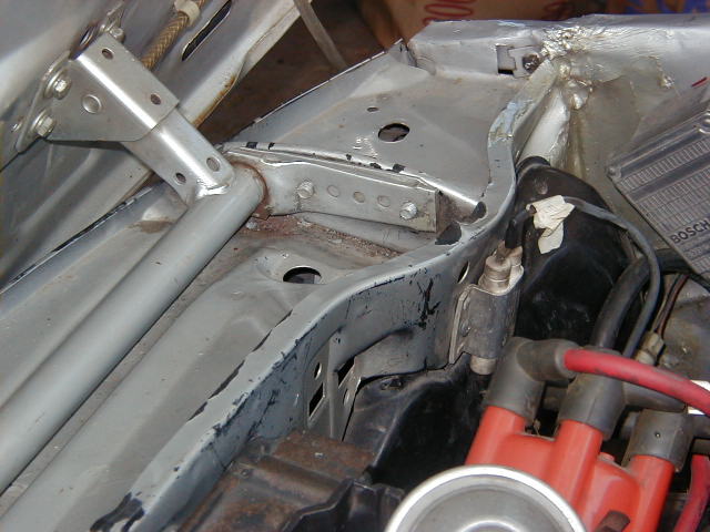
Remove
Hood |
Removal |
Remove
the 4 bolts that secure the brackets to the car. (Not hood) Undo
the 2 bolts that hold the elbow limit braces.
Disconnect the window washer hoses. Remove
the hood and store it in a safe place. You don’t want it falling over. |
|
|
|
Remove
Battery |
Removal |
Disconnect
the battery, remove it, and store it. |
|
||
|
Drain
Coolant Remove
radiator |
Removal |
Drain
the coolant. There is no petcock on these radiators so it can be
messy. Remove a temp
sensor at the lower hose to drain radiator.
Undo 19mm bolt at passenger side of block beneath #6 sparkplug to
drain block. The
plastic fan shroud has 2 sheet metal screws at top and tabs at the bottom.
Undo screws. There is
a 10mm screw at passenger side bracket.
Remove bracket. Undo
top and bottom hoses. Undo
wire spade connectors at thermo sensors near lower hose.
Radiator should pull upward with some jiggling.
Remove shroud. Place a piece of masonite where the radiator was to
protect the condenser from being hit (if you have A/C). |
|
||
|
Label
Injection Wiring Harness Points |
Removal |
Here
is where you really want to pay attention and label whenever you can. There
are really not too many connections on the motor. The biggest problem is
that all the wires are the SAME COLOR for the injection harness.!!! We
snapped some pics before doing this… Might be useful later? Be
sure to label all of the thermo sensor wires. |
|
||
|
Label
Chassis Wiring Harness Points |
Removal |
Oil
Pressure sender, starter, alternator, ground at thermostat cover, ignition
wire at distributor, transistor box multi-plug, coil, AC connector.
For 79 the front and rear runners had to be removed to undo the
wire harness. |
|
||
|
Chart
Manifold hoses |
|
Make
a diagram of all manifold vacuum hoses and cold start connections.
(Aux air valve) Even better, label the hoses. Remove
them. Check them for age and
cracks. Mr.
Dun Rite: |
|
||
|
Remove
AFM |
Removal |
Remove
air cleaner assembly, AFM multi plug , and AFM. Take the rubber bellows off the throttle body. |
|
||
|
Undo
Throttle Linkage |
Removal |
Undo
pop-on connectors at fire wall and from bell-crank to throttle body.
Note the position and orientation of the rods. |
|
||
|
Remove
Throttle Body |
Removal |
Undo
4 nuts 10mm. Cut the 2 small
water hoses and undo crankcase vent hose from cam cover. Doing so allows easy access for disconnecting the plastic
injector plugs.
Disconnect the throttle position plug connectors.
Be sure to label them. Idle
& WOT. Remove
the accelerator rod. |
|
||
|
Remove
Injection Wire Harness |
Removal |
Remove
the plastic thermo and injector plugs.
We found that a “pick” type tool works well for this. Be
prepared to catch the clips as they fly… (spring steel)
Cut wire ties at firewall. Work your way from the front of the
motor to the rear. Disconnect
and label the wiring from the engine main harness along the valve cover.
This includes the injector wires, WOT (already disconnected from previous
step), cold start injector sensor, coolant temp sensor, oil pressure
switch, etc. The locations of some of the sensors vary depending on the
model year you are starting with. Drape harness on windshield, secure with
wipers. Pull
computer plug from glove box if installing Motronic.
PC tried for fun and could not figure how it pulls out - so good
luck. |
|
||
|
Remove
Chassis Wire Harness |
Removal |
Undo
starter wires, undo alternator wires, undo dipstick wire holder, undo wire
stays at intake runners. Secure
out of the way on the wheel well. The
wire harness from the distributor/ignition module can be routed onto the
top of the radiator support and out of the way. You may want to tuck it
behind the masonite protecting the condenser. |
|
||
|
|
Remove
Fuel Lines |
Removal |
Remove
the fuel lines from the pressure regulator and the rear of the fuel rail.
Label them for re-installation. Remove
and label the vacuum lines from the pressure regulator. Remove
the fuel line from the cold start injector. |
|
|
|
Remove
Brake Booster Hose |
Removal |
We
had to cut this hose near where it attaches to the log manifold.
Be careful to preserve this hose.
It is difficult to find a replacement. This
is special “anti collapse” hose so don’t skimp on replacement!
We’re talkin’ brakes here! |
|
||
|
Map
Coolant Hoses |
|
Coolant
hoses vary from year to year. Pay
special attention to the heater formed hoses and connections. This
is especially important if you have the “Jules Verne” plumbing under
the intake pipes like Sean’s car has(1979). |
|
||
|
Remove
All Coolant Hoses |
Removal |
Remove
the heater hoses that go to the heater unit. Remove
the coolant hose from the filler (expansion) tank. If
stuck, cut them off especially at the firewall and the smaller hoses.
Save
all hoses and label for the hunting and gathering of new replacement
hoses. |
|
||
|
Power
Steering Pump AC
Pump |
Removal |
Remove
with 3 -17mm bolts. It stays
on the chassis. Wire out of
the way. Remove
top adjuster bolt and 2 bottom 17 MM bolts.
It stays with the chassis. Disconnect
the wire if you have not done so. Remove
the belts. A/C, P/S, Alt. You may want to mark them so you know which ones
are for what later. (Of course
you’ll want to put on new ones! Mr. DunRite) |
|
||
|
Remove
Cooling Fan |
Removal |
With
radiator out, remove fan from water pump. 4 -10mm bolt. Remove the cooling
fan and fan clutch. There are two different styles here. Sean had the
older style pump with 1 – 10mm bolt
thru the fan clutch. (This will determine which way you may want to go
when you replace the water pump. More
on this later.) |
|
||
|
Remove
Distributor |
Removal |
Set
engine at Cylinder #1 TDC (See Timing Marks on Damper).
Release 10mm clamp bolt. Distributor
spins counterclockwise up and out. Now
would also be a good time to remove the cap, Ignition wires, and the
distributor. Take notice on
the position of the vacuum advance on the distributor and also observe the
rotation of the rotor as you remove the distributor. This will help on
reinstall. Tape over the dist. hole with duct tape. Don’t want any
“smeg” going in there. (“smeg”-
besides the biological stuff, it is also the stuff that is covering your
engine at this point. Grease/Grime/Dirt = ”SMEG”) |
|
||
|
Chain
Engine to Hoist |
Removal |
Using
the front hoist tab and the hole in the engine block above the starter,
hook or (better) bolt a chain.
If these locations aren’t accessible, you’ll need to find
suitable locations to connect to the motor. Be sure you are not bending or
rubbing any crucial parts when you lift.
Set chain so it does not press against the fuel rail. Once
you get the chain attached, you should be able to get the hoist to lift it
almost straight out of the engine bay. You may want to have a slight tilt
UP at the front of the motor. You should have enough space to get the
motor out with the clutch still on, but with the bellhousing still on
you’ll have a VERY tight squeeze (See memo on tranny or not). Another
thing to think about, make sure your hoist can be fully extended as
you’ll need to lift the motor very high to get it over the front of the
car without lowering it off the blocks. |
|
||
|
Undo
Engine Mounts |
Removal |
Undo
4 - 17 MM nuts top and bottom. |
|
||
|
Double
Check |
|
Take
a minute, maybe stop and have a beer, and check that all wires, hoses,
etc. are disconnected, labeled and out of the way. |
|
||
|
|
Under
the car ... |
Removal |
There
are several different tranny/engine removal sequences available for your
home mechanic pleasure. We
will go with the most labor intense/ easiest engine yank.
(In Sean’s own words) (By
the Sean feels very strongly about PULLING the TRANNY FIRST!) |
|
|
|
Exhaust
Downpipe |
Removal |
Undo
3 nuts from rusty manifold studs from under the car.
Be gentle so you do not damage the studs.
Use liberal amounts of Liquid Wrench starting a week prior to
removal. Undo the hanger
above the fuel pump and the rubber donuts at the rear. Remove
Oxygen Sensor. Remove the Heat Shield. On
Sean’s car the Exhaust system came out in one piece. It was pretty
simple to remove but a bit cumbersome to move around. |
|
||
|
Undo
all rear tranny Connections |
Removal |
Remove
the 3 Guibo (Rubber Donut) nuts and bolts.
Disconnect the shift levers and remove the shifter. There is a 10mm
bolt up high. Remove
speedometer cable. Remove the
clutch slave cylinder 2 – 13mm nuts and the clutch hydraulic line keeper
at the bellhousing. One
17mm bolt. Remove the reverse
sender wires above the clutch slave. |
|
||
|
Remove
the Tranny |
Removal |
Undo
the 4 - 17mm nuts at the tranny to bellhousing. You need a special “C” or “S” shaped box wrench to
get this bitch of a nut loose. Tilt engine up on hoist. Tranny should slide out from bellhousing.
The tranny is heavy, so be carefully of your body and fingers. The
drivers top left nut may be a candidate for a weeks worth of liquid wrench
prior to removal. |
|
||
|
Undo
the Bellhousing |
Removal |
With
the tranny out, you now have access to the bolts securing the bellhousing
to the engine. Starting at
the oil pan, there are 3 - 10mm bolts that secure the bottom cover plate.
More than likely they are covered with crud, smeg, and slime.
There are 17mm bolts at 4 locations and 13mm bolts at 3 locations
holding the bellhousing to the engine.
The aluminum bell housing slides right off.
|
|
||
|
Extract
Engine from Bimmer |
Removal |
With
a slight upward tilt, whilst wrestling the AC pump out of the way, you
should be able to lift the engine up and out of the bay without
interference from the top of the radiator bulkhead. Boy
wasn’t that easy ! It
only took three of us, 4 hours to get to this point on Sean’s car.
PC’s took 8 as he was “on his own” and
it was his 1st time
around. |
|
||
|
Position
2.8 for ease of Access |
Removal |
You
will now be removing many more parts from the 2.8 for transfer to the 3.5
than you thought. Remove
the alt. And store. Remove
the brackets for the steering pump, alt, and a/c. Remove
the clutch and discard. Remove
the flywheel. You may need to improvise here to get the bolts out. An air
impact wrench will help here. Remove
the exhaust manifold(s). These nuts may need to be soaked with “liquid
wrench” in advance. You’ll
probably need to replace these on the 3.5 motor, so don’t worry to much
about breaking the studs. Remove
the motor mount flanges from the engine block. Remove
the cold start injector and spacer Remove
the 6 “C” intake runners. Remove
the “log” from the top of the intake. Remove
the injector holddowns. (remember to “bag and tag” the bolts, spacers,
washers, etc!) Remove
the injectors, the fuel rail and injector manifold as one unit. Remove all
of the coolant hoses. On the 79 engine we removed this, which also led us
to the removal of the coolant jacket for the Aux. Air Valve. See the pic
as this one looks like a spider web. This housing also has the temp-time
switch and coolant temp sensor. On the 80 and newer models the Aux. Air
valve/sensors are located on the valve cover and thermostat housing
respectively. The coolant piping is different between these years as well.
We used the stock setup on re-assembly(for Sean’s 79) so piping here may
need some improvisation. Remove
the dipstick. Remove
the oil filter housing from the block. Remove
the oil pan. Lots of bolt here… Remove
the thermostat Remove
the water inlet housing. Remove
the starter If
you are doing a Motronic conversion, you can skip several of these
steps but you still need to move a lot of parts. |
|
||
|
|
|||||
|
|
|||||
|
|
|||||
|
|
|||||
|
|
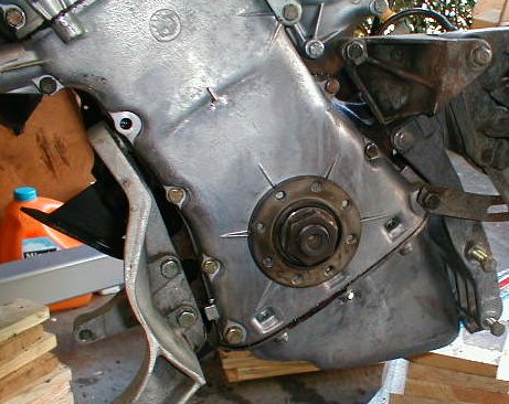
Front
Timing Cases Upper
and Lower |
Engine
R&R |
UPPER
- Remove the large nut in the side of the lower timing case. It is spring
loaded to holds the timing chain damper.
Remove the 6 front bolts from the Upper Timing cover. There are
also 2 smaller bolts connecting the upper cover to the lower, remove these
as well. The cover may need a bit of coaxing to get it off (rubber mallet
works well here). The Distributor drive gear is housed in this cover, it
should come out of the front of the cam pretty easily. There may be a bit
of tension on this as there is a rubber O-Ring on the drive gear shaft
(inside the cam). LOWER
- (Optional) This means you’ll have to remove the harmonic
balancer/pulley assembly from the engine. 8 – 13mm bolts.
You will have to undo the 325 Ft LB crankshaft “mother” nut.
We used an air impact wrench to get this nut off. There are other ways to remove it, but we think it puts too
much unneeded stress on the crankshaft. Use a gear puller to remove the
hub. Install
a new front seal. Remove
the old seal from the lower case. This may require a hammer and punch. Be
careful not to “nick” the case. Using wood blocks to hold the case
will help. Insert the new seal, DRY. Use a large socket around the edges
of the seal to hammer it in (tap it in per PC). Use
gasket sealant and place the new timing case gaskets onto the case. Coat
both sides, but not the top (where the upper case meets it) and not the
bottom (where it meets the oil pan). Insert and tighten the bolts that
don’t have brackets to be included (this is the reason to LABEL
everything…) Install
hub and retighten crankshaft bolt to 325 FtLbs with air impact gun.
Don’t forget to wipe a bit of oil on the rubber part of the seal before
putting the case on. Mr,
Dun-Rite The
L Jet & Motronic are very sensitive to engine vacuum which includes
the entire sump and head volumes of the engine.
Replacement of the crank seals is an easy procedure to insure
100’s of K miles of vacuum tightness. |
|
|
Rear
Crank Seal |
Engine
R&R |
The
seal is held by a cast aluminum housing.
The seal can be removed with a pick.
Check the crank for grooves. If
present, try to locate the new seal wiper on unworn surface.
Apply a finger of oil to the seal part touching the crank.
Lightly tap into place incrementally using a piece of wood and
small hammer. Try not to deform it. There is also a spacer ring that may
be in there. According to the BMW parts guy we spoke to, that part has
been omitted. we didn’t use it… but that will be your call. You’ll
want to remove the oil pan bolts here too. Cut away the old gasket. Mr,
Dun-Rite If
you go the housing route, apply “form a gasket” to all mating surfaces
of the aluminum housing to the cast iron block to insure a vacuum tight
installation. Dunrite!
Sean also changed the gasket on the
oil seal holder as well. ( This is one part he forgot to get in advance.
Had to run out and get it or we were done for the day. Wasted 3 hours.) |
|
|
|
Flywheel (L
jet specific) |
Engine
R&R |
Surfacing
..... You
need to get your flywheel surfaced at a machine shop(remember we are using
manual trannys…). They will
take approx. 20 thousandths off. Sean’s
required surfacing at the shoulders, thus the 3 pressure plate locating
pins had to be removed. PITA.
Replace the pins when done. You
may need new ones since you may ruin the existing ones extracting them. Installation
... There
is a locating tube at one of the 8 holes.
Thread in all 8 -19 mm bolts coated with Loctite.
Torque to 73 Ft Lbs in stages of 10 lbs..
The bolts had a nice feel as we did the last round of torque to73
FT Lbs. To
hold the flywheel when tightening use a flywheel holder (time for a new
tool anyway). Mr.
Dun_Rite Purchase
new bolts from the dealer for this critical application. The
Loctite is an important step toward eliminating vacuum leaks in addition
to holding the flywheel to the car at higher RPM’s. (Loctite is an epoxy
that cures in the absence of oxygen) ***
Make sure you use both sealant and thread locker on the flywheel bolts.
This is a crucial step as if you don’t use sealant, you will have an oil
leak, and think it’s the rear seal. The bolts WILL leak.
|
|
|
|
Pilot
Bearing |
Engine
R&R |
Apply
Loctite to outer surface of the Pilot Bearing. Gently tap it into position using some wood and a hammer.
We could not determine the optimum depth to set the bearing at. Note:
We both had donor engines with automatics, hence no existing pilot
bearings. Here are three
techniques for removing a pilot bearing that refuses to come out .... 1)
rent a removal tool, it looks like a slide hammer, or lock extractor. 2)
Fill the space behind the pilot w/ Black Cats, light the fuses and
voila! (Wear goggles for this method! And KEEP YOUR MOUTH CLOSED!) 3)
Fill the volume behind the bearing with packing grease.
Find a wood dowel that matches the pilot hole take a hammer and?…
(hydraulics) |
|
|
|
Clutch,
Pressure Plate |
Engine
R&R |
Using
the nifty plastic clutch tool, set the clutch plate and the pressure plate
on to the flywheel. There are
3 locating pins for the pressure plate.
Thread the 6 – 13mm or (6 mm allen) bolts.
Tighten evenly in 4 or 5 sequences till the pressure plate is snug
to the flywheel. Torque to 17
FtLbs. Slide the clutch tool
in and out during this sequence to insure that the clutch disc is evenly
centered on the pilot bearing. Sean
and I both used the Sachs “Super Set” clutch kit which comes with
everything you need to do a complete clutch job..
We paid $180. There
may be a 3.5 pressure plate that is a little stronger than the 2.8.
Sean is using the 2.8 and it works just fine for everyday driving. |
|
|
|
Timing
Marks on Flywheel |
Engine
R&R |
Mr,
Dun-Rite Apply
white and yellow paint 2 inches beyond the stainless balls and between the
stainless timing balls. This
will make it very easy to find the marks through the bell-housing view
port. |
|
|
|
Engine
Mounts |
Engine
R&R |
Bolt
up your 2.8 steel mounts to the cast iron block bosses. 17mm bolts. Based
on uniformed opinions, all M30 blocks have bolt bosses that will take the
E 12 engine mounts. At least
thru 1987 engines. |
|
|
|
|
Oil
Pan |
Engine
R&R |
The oil pan has to fit the E12 chassis and cross bar. Most later E28s do not fit. Some earlier 733, 633 etc. May fit. The E28 & E24 oil pans are approx. ½” or 10mm deeper than the E12, they also have better baffles. If your new pan looks like it might fit, chain new engine on engine hoist and do a trial fit. Replacing the oil pan gasket is infinitely easier with the pan out of the car... clean it spanky clean. (this
pan is why you want to do a conversion!) |
|
|
Oil
Pick Up |
Engine
R&R |
If
using your E12 pan, the oil pick up needs to be transferred from the 2.8
engine. The E12 pick up is
approx. ½” less deep than the 3.5 pick up. The tabs holding it are
different from the E12 so you may need to improvise a bit. There are 3
-10mm bolts that secure it to the oil pump.
There is a thin metal gasket that fits between the pump and pick
up. All 10mm bolts. You
will need to remove the 3.5 oil pick up. It is held by 4 bolts on the pump
and 2 on a support bracket. Don’t remove the end cap to take off this
support bracket. It is easily bent out of the way to remove the pickup. |
|
|
|
Oil
Pan Install |
Engine
R&R |
Lightly
screw all of the 10 mm bolts back in.
Starting at the middle (Cylinders 3 & 4) tighten the bolts in a
pattern working outward in both directions to avoid creating any weird
stresses in your beautiful aluminum casting. Use Sealant/gasket cement on
the pan gasket. Put the pan back on. Tighten the bolts evenly, and don’t
over tighten. If you crush the gasket too much you may have leaks. There
are different schools of thought for gasket sealing.
We both went with coating both sides of the oil pan gasket.
I used copper RTV, Sean used liquid “form a gasket”, we will
see whose is better. Avoid
applying too much sealer as it might get stuck in an oil passage. It
appears that trying to replace the gasket with the engine in the car is
next to impossible so why worry if a one sided application facilitates
future servicing. |
|
|
|
Harmonic
Balancer |
Engine
R&R |
Before
installing harmonic balancer... The
Alternator, AC Bracket, Power Steering brackets all have bolts thru the
lower timing case. The 3.5
balancer blocks access to the bolts.
Secure the bolt for each bracket.
Be sure to keep track of the correct bolts.
The bolts through the timing case are all special lengths. 13mm
bolts.
The
balancer has a locating pin to reference it to the crankshaft TDC.
The pulley holes are eccentric (not evenly spaced).
Rotate the pulley until all of the holes align.
Install and evenly torque the
8 - 13mm bolts. The
3.5 balancer is larger than the 2.8.
Be sure your engine monger includes it in the deal.
We could not get an opinion it is important to use the 3.5 balancer
or not. |
|
|
|
AC
Bracket |
Engine
R&R |
Install
the AC bracket. 2 -17mm bolts
to the block and 2 -13mm bolts thru the timing case. |
|
|
|
Engine
Diagnostic Sensor |
Engine
R&R |
You
need the sensor bracket off of the 3.5(due to the larger balancer).
One of the bolts also secures the AC Pump adjusting bracket.
One of the bolts is extremely long.
13mm x 45 mm |
|
|
|
|
Water
Pump Fan
Pully |
Engine
R&R |
Install
with new gasket and 4 - 10 mm bolts.
We strongly recommend a new water pump. $50 There
is a Catch 22 .... (There
two types of fan clutch mounting systems which affect the model of pump
that you use. The E12’s
have a single 10mm bolt to secure the fan clutch to the pump.
That old style fan clutch costs $125 for replacement.
A newer style fan clutch has a large gland nut that spins onto a
large thread on a newer style water pump.
New style fan clutch $75. You
will also need a newer style fan pulley, the hole spacing is different.
It is vastly easier to remove & replace when radiator is
installed) |
|
|
Special
Conversion Nut (L
Jet required) |
Engine
R&R |
There
is a special nut that threads onto the end of the 3.5 camshaft with a slot
milled to accept the spade end of the distributor drive. Put the
“giant” nut onto the cam. Use a bit of
thread lock. Torque to
the end of the cam. 32
or 36 mm. It is big. (Cannot
remember) We paid $45. You
can use channel locks to grip the bolt.
Or go to Sears and get a $20 socket (PC) or a $20 open end (Sean). |
|
|
|
Upper
Timing Case (L
Jet required) |
Engine
R&R |
Install
the nut, spring, ball and piston for the timing chain damper. Use a good
amount of oil on these during assembly. If
L-jet, you need to re-use upper timing cover from the 2.8 for
the distributor drive. . Put the NEW O-ring onto the distributor
drive and coat with a bit of oil. This O-ring is important for engine
oiling (don’t skimp here get a new O ring!). Insert the drive gear into
the cam end. Oil the 2.8
distributor driver shaft and insert into cover. Install cover with new gaskets at sides and the bottom.
Loosely install the 6 – 10 mm side bolts then thread
the 2 – 10 mm bottom bolts.
The bottoms were difficult to get threaded.
Evenly tighten with a very light torque.
(Note;
the L Jet timing cover requires re-use of the 2.8 cam-cover.
The front bolt holes are different.
The gasket is
different from the Motronic cam -cover.) |
|
|
|
Starter |
Engine
R&R |
Clean
up the 2 - 17 mm nuts. Apply
oil or graphite. Do not
overly tighten the top bolt. (a) Apply
dielectric grease to the electrical connections. (When you go back to change your starter with the engine in the car
you will appreciate this instruction.) |
|
|
|
Accessory
Bracket |
Engine
R&R |
Bolts
to block, timing case and bottom of oil sump. Use the 2.8 bracket to insure that all of your 2.8
accessories (alternator & PS Pump) will fit correctly. |
|
|
|
Alternator |
Engine
R&R |
Replace
the rubber sleeve if it is worn. Someone
mentioned using a polyurethane sleeve that would never wear out. Secure alternator loosely to the adjusting bracket which
you installed prior to the balancer. The
alternator can go in after the engine is in the car.
It is easier out of the car. Make
sure you use a new bolt of the correct length because once in the car,
adjustment of the alt. position is strictly by braille.
The PS pump limits your access to the adjusting bolt. Mr.
Dun Rite |
|
|
|
Oil
Filter Boss |
Engine
R&R |
You
may need to move your E12 boss over depending on the oil filter set up
from your donor engine’s previous set up. (There
has been considerable discussion on this subject, depending on the donor
engine used. Up to 1987, you should be able to use the 2.8 mount directly.
After 1988 we’re not sure. If you see any additional oil ports on the
block, write to FirstFives.org list and discuss it there). |
|
|
|
Intake
Manifolds L
Jet Specific |
Engine
R&R |
Install the Injector manifolds and the injector assembly.
Install the runners. Use new paper gaskets at all connections. (We used the single gaskets per port.) Leave all of the bolts loose so that you can evenly snug down all of the joints (12 in all) evenly with everything aligned. Again you are preventing vacuum leaks. PC’s has a combo of 13mm nuts and 12mm nuts, Sean’s had all 13mm nuts.
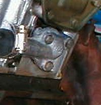
Install
the "log" manifold. Do not forget the
2 triangular brackets that keep the log manifold supported. You may need
to bend the supports a bit to get the log into position (see the pic ). We
did not do the Motronic manifold but it bolts right up. |
|
|
|
|
320i
Runners L
Jet Specific Optional |
Engine
R&R |
The
runners come with stiffeners and with out.
The stiffeners interfere with the fuel rail and need to be notched.
In either event, you need to come up with a custom bracket(s) to
hold the fuel rail semi rigidly in place. As
noted in GRM the hot set up is to replace the 528 intake runners with
runners from a 320i. The
longer runners definitely make a positive difference in the 2000 to 3000
RPM range. Not to mention they look way cooler. |
|
|
Water
Inlet Cluster |
Engine
R&R |
This
puppy has to go on after the intake manifolds. Clean the port of gasket
material. We used the 3.5 housing as the one from the 2.8 was kind of beat
up. It also has all the same sensors in it that are located near the Aux.
Air valve. If I ever decide to change the plumbing on the side of the
engine from the 79 version to an 80-81, the wiring can be moved easily to
the sensors in the thermostat housing. Use
a new paper gasket. 3 - 13mm
nuts. Note: the top nut
secures the diagnostics plug bracket. |
|
|
|
Secondary
Hoses |
Engine
R&R |
It
is way easier to install the secondary hoses that mount beneath the
manifold and the heater hoses with the engine out of the car.
Leave the heater hoses loose and be careful how you orient the
clamps since access in the car is cramped. Mr.
Dun-Rite We
replaced all of our hoses with new through out.
BMP is the hot set up with a set of all new correct hoses for less
than $100. |
|
|
|
Hot
Water Plumbing L
Jet Specific |
Engine
R&R |
The
L Jet has a hot water loop at the bottom of the throttle body to warm idle
air. Most likely this is a
smog related item. The 3.5
blocks do not have a water supply port above the starter like the 2.8
block. The simple solution is
get a plastic “T” from NAPA and cut into the heater supply hose. Mr.
Dun Wrong |
|
|
|
Aux.
Air Valve Plumbing |
Engine
R&R |
Pre 80, the L Jet uses a water temp sensor located beneath the intake manifold runners cobbled into the heater/reservoir return piping for cold start operation. 80/81 uses an electrically operated idle air control for cold running that is a much cleaner install. If possible, get the parts off of a wreck. See The FAQs For Aux Air Valve Descriptions. |
|
|
|
Exhaust
Manifolds |
Engine
R&R |
Clean
the threaded studs with a wire brush.
Use new gaskets. Use a
graphite anti seize compound on the studs.
(For when you install those new “ extrude honed” ported E28
manifolds later on). Snuggle
manifolds onto studs and secure with bolts. Sean
and I re-used our 2.8 manifolds since we were reusing our 2.8 exhaust
systems (and need to meet CA smog laws). According to all of
the bulletins, there are countless horses waiting to be unleashed with a
proper 3.5 manifolds or headers, and a free flow exhaust setup. Mr.
Dun Rite |
|
|
|
Water
Drain Plug |
Engine
R&R |
19mm
– Bolt into place using a new washer or RTV.
Mr.
Dun Rite |
|
|
|
Heater
supply port |
Engine
R&R |
At
rear of head beneath Rear Cam Cover.
Use E12 unit to be compatible with the preformed E12 heater supply
hose. New gasket and RTV, 3-
10mm bolts. Loosely install
supply hose. Orient clamp so
you can get a screw driver on it when engine is in car. This
part is impossible to get at with engine in the car.
Advanced Braille is required for R&R. |
|
|
|
Rear
Cam Cover |
Engine
R&R |
There
is a stamped metal plate with a gasket and a fiber washer on one 10MM bolt
that will leak sooner or later. Replace
the gasket and install the fiber washer on the bolt gasket closest
to the exhaust side of the head. This is also refered to as the
“duck” gasket. Mr.
Dun Rite With
engine installed this cover can only be R&R’d by braille.
Due to its immediate proximity to the firewall. |
|
|
|
|
Damper
TDC |
Engine
R&R |
There
are 2 lines in the Damper for showing TDC.
Paint them white or red. This
is a good time to turn the engine to TDC cylinder one for your eventual
distributor installation. (After the engine is in the car) |
|
|
Fan
belt |
Engine
R&R |
Install
alt. / water pump fan belt. Record
it’s size. Make sure you
have an adequate range of adjustment for the alternator.
Fan belt sizes vary. The
power steering and AC belts go on once the engine is reinstalled. Mr.
Dun Rite |
|
|
|
Cam
Cover |
Engine
R&R |
Install
to protect valve train. As
noted previously, the L Jet and the Motronic camcovers are not
interchangeable. The front
bolt hole is located differently. The
2.8 & 3.5 gaskets are different. |
|
|
|
Spark
Plug Holes |
Engine
R&R |
While
easy to get at, check that the spark plug threads are clean,
are not cross threaded, and
are operating easily. If
not, now is the time to clean them with a tap or heli coil. |
|
|
|
Engine
Out of Car |
|
Since
the engine is out of the car, you might want to clean the engine
compartment. Use some type of “gunk”. Protect the wiring as best as
you can from water saturation. Clean and paint any surface rust with rust
inhibiting paint. Clean out the A/C condensor (if the car has a/c of
course). Fix any insulation on the firewall that is ripped. |
|
|
|
Engine
/ Transmission Installation
techniques |
|
See
Notes on your options for engine / tranny combinations for reinstallation.
Each has its advantages / disadvantages. (See Pics Below at "hoist mounting") |
|
|
|
AC
Condenser |
Install |
Place
a piece of plywood to protect the delicate aluminum fins while
reinstalling the engine. |
|
|
|
Rubber
Engine Mounts |
Install |
Place
loosely bolted on the frame mounts. Do not tighten. You will need to be
able to move them around during your engine docking procedures. Mr.
Dun Rite Install
new OEM rubber mounts. I f
yours are over 100k miles old, they are most likely shot. |
|
|
|
Chain
Hoist |
Install |
Secure
chain to water pump lifting steel tab and to hole in flywheel casing above
starter motor. Make sure the
rear is easy to undo with the engine in the car, hand access is limited. |
|
|
|
|
Hoist
Mounting |
Install |
The
angle at which you set the engine at depends on tranny or no tranny and
how high you have the car jacked up off the ground. You may have to do 2 or 3 trial attempts to get a
successful insertion. The
clearances are very tight. Lower
the engine SLOWLY! The tricky part is to get the Motor Mount flanges lined
up with the mounts themselves. The A/C compressor and P/S pump may need to
be moved a bit to get the engine all the way down. Once
it’s down correctly, make sure to put the nuts onto the mounts. You
don’t want the engine lifting off of the mounts when working on the
tranny reinstall. Mr.
Dun Rite:
Cut
up a piece of plastic garbage can or similar that matches the profile of
the tranny hump. Use it to
protect the foil and rubber shielding while cramming the engine back into
place. |
|
|
Bellhousing |
Install |
If
you left the bellhousing off now is the time to install it while the
engine is at an angle and in the car.
(Don’t worry about the engine resting on the pan, it is very
strong and appears to have been designed to do this function.) It has 4
– 17mm bolts and 3 – 13 MM bolts all special lengths.
Do not forget the clutch lever and the throw out bearing. There
is a stamped metal crescent moon piece at the bottom of the bellhousing.
3 - 10 mm bolts. Secure before the engine is in final position for ease of
access. The cross member
makes access to these bolts difficult. We
made a custom bracket that bolted into the clutch slave location with a
long 10 mm bolt that pressed against the clutch lever bar to keep it tight
against the pressure plate. Just
some 1 x 1 alum angle drilled and tapped.
Otherwise it flops around and is a real PITA. |
|
|
|
Tranny
Options |
Install |
a)
In theory you can leave the tranny in position and gently drop the
engine so that it slides onto the input shaft. There is not enough fore and aft clearance to accomplish
this easily. b)
If you pulled the tranny, now is a good time to slide the input shaft
home while the engine is still at an angle.
c)
The tranny is secured with 4 – 17mm bolts. The dreaded bear of tranny world is the driver side top
left bolt. Gertrag threw too
many casting fins for any access. The
remedy is the magic "S" or "C" wrench(es). |
|
|
|
Temp.
Tranny Support |
Install |
You
will need to support the rear of the tranny. Reposition
your jack to hold it until you are ready to install the cross member. |
|
|
|
AC
Pump |
Install |
Before
dropping the engine to the mounts, position the AC pump in the correct
position. Ease the engine
down until you can set the 2 - 17mm bolts that secure the bottom of the
pump. Install the electric
clutch wire. This
step is so easy to write about! Wrestling
with the heavy AC pump is a definite PITA. |
|
|
|
Engine
Mounts |
Install |
With
the above done, lower the engine onto the mounts, you may have to jiggle
the rubber engine mount studs to engage.
(You
did leave them loose?) Check
the engine and tranny for clearances and alignments before dropping all
the way onto the mounts. 17mm nuts. 4
total. |
|
|
|
Rubber
Donut (Guibo) |
Install |
Set
the three 17mm bolts that secure the Guibo to the tranny output flange. If
they will not go together, you have not dropped the engine correctly or
you need to loosen the spline gland nut near the driveshaft center
bearing. Mr.
Dun Rite:
The
manual says to use new bolts and aircraft style nuts. Get from dealer. Replace
your Guibo with a new OEM unit if it is over 75k miles old.
Don't
remove the strap (if new) until it has been bolted to the driveshaft and
tranny. If used,
use 2- 6” PVC hose clamps to compress the Guibo. |
|
|
|
Gearshift
& “poopdeck” |
Install |
While
the tranny is slightly dropped, bolt the sheetmetal gearshift
“poopdeck” to the rear of the tranny 2 – 10 mm bolts and install the
gear shift levers. There is a
rubber bumper at the rear of the “poopdeck” that bolts up to the
transmission hump. Do not
forget the molded foam insert for noise control. |
|
|
|
Reverse
Light Sensors Speedometer |
Install |
Secure
to top of transmission while slightly dropped. Install
speedometer cable fitting. Secure
with special 10 mm bolt. |
|
|
|
|
Transmission Crossmember |
Install |
Install
at sliding rails flanking the transmission hump. 2 – 10mm special bolts and nuts. Leave loose. Secure
rubber tranny mount w/ 17mm bolt. Check
that tranny and driveshaft look aligned.
Tighten rail nuts. Mr.
Dun Rite:
How
do you know if things are aligned when you upside down on a creeper under
the car with a greasy nose? |
|
|
Install
clutch slave |
Install |
Install
with 2 – 10mm nuts to studs on the bellhousing. Secure hydraulic line to tab on the bellhousing.
15mm bolt. PITA. Mr.
Dun Rite:
If
your clutch slave is over 100k miles old, it is time to replace it. |
|
|
|
Exhaust
Downpipe |
Install |
Using
a new gasket(s) install downpipe to headers.
3 nuts onto rusty studs. Use
a die to sweeten up the stud threads.
Use graphite thread compound.
Secure exhaust pipe at transmission hanger. Mr.
Dun Rite:
Get
3 new copper nuts from your dealer or parts monger .They do not rust. |
|
|
|
Oxygen
Sensor |
Install |
Install
at downpipe. Use gloves, do
not touch the white ceramic tip. Install
a new unit to simplify tuning. |
|
|
|
Power
Steering Pump |
Install |
Install
pump to accessory brackets. 3
– 13mm bolts. Install belt.
Adjust tension and tighten adjusting bolt. |
|
|
|
AC
Pump |
Install |
Install
adjusting bolt and nut to sliding arm from timing case.
13mm. Install fan belt
and adjust tension. You can
use your handy 18” ratchet bar to lever the pump / fan belt tension.
|
|
|
|
Install
fan (If
old E12 style) |
Install |
Needs
to go on before radiator is installed. |
|
|
|
Chassis
Wiring Harness |
Install |
Install
the wiring that feeds from the drivers side.
It connects the oil pressure sensor, the alternator wiring, engine
coolant sensor and ground, it wraps around the front of the engine,
distributor wire, ignition and coil wiring.
It secures to the dip stick & the distributor.
Use plastic wire ties at the distributor splash plate. Mr.
Dun Rite: Use
dielectric grease at all connections. |
|
|
|
Ground
Strap Alternator
Ground |
Install |
Secure
to driver side engine mount bolt. Secure
to engine. Check for
condition of wire and connections. If
disreputable, replace for future electrical happiness. Mr.
Dun Rite: Use
dielectric grease at all connections. |
|
|
|
|
Starter
Wiring |
Install |
Connect
the starter wires 2 spade connections and 1 - 13mm bolt. Use
dielectric grease at all connections. |
|
|
Heater
Supply / Return Hoses |
Install |
Secure
to firewall plastic hose nipples. Orient
hose clamps so you can get an extra long screwdriver on them parallel to
the fire wall. |
|
|
|
Lower
Radiator Hose |
Install |
The
mounting of this hose is critical. The
clearance at the bottom radiator to the AC Pump pulley is very tight so
the hose must be angled and positioned correctly.
Further it is bear to get it onto the thermostat housing intake,
further the clamp position is important for screwdriver access, further
the dealer OEM hose we got was 2” too long and had to be cut to size.
Leave hose loose until the radiator is installed. Make
sure the hose does not rub against the AC pulley.
|
|
|
|
Radiator
and fan shroud E 12 OEM |
Install |
Install
your radiator on the factory rubber pads.
Slide as far to the passenger side as possible.
Check the bottom hose for clearance at the AC pump.
PC had to install a wedge under the right side of the radiator to
tilt it up away from the AC (hose grinding) pulley.
Secure pass. side bracket with 2 - 10mm sheet metal bolts.
Attach lower hose. Attach
temperature sensor spade fittings near lower hose. Slide plastic shroud into position, there are two tabs at
the bottom of the radiator. 2
– sheet metal screws at top.. The
E 12 brass OEM radiator is easily replaced with an E28 aluminum 535
radiator that has more cooling capacity.
It mounts in the same position however the brackets are different
and require some minor sheet metal cutting and drilling.
You need to use the 535 top and bottom hoses because the radiator
nipples are different. The
going price seems to be around $125 for a used unit. |
|
|
|
Upper
Hoses |
Install |
Install
upper hose and small diameter reservoir hoses. Attach heater return manifold hose to reservoir. You
can use fuel hose for the radiator return. |
|
|
|
Brake
Booster Vacuum Hose |
Install |
Reattach
brake booster hose to manifold. Clamp
tightly. We
both had trouble with this hose. It
is stiff, un-yielding and gnarly. We
had to cut it off the manifold. We
got some hose off a wreck to replace the portions that we had cut.
It is designed for extreme vacuum pressures. The dealers have
trouble getting it. Sean was able to obtain some new, but it was pricey! |
|
|
|
Throttle
Link |
Install |
Grease
ball joints and install. They
snap into place. Connect at
firewall and from bell crank to throttle. PC
now own a 533i with a cable linkage.
The visceral feedback from the E 12 hard rod linkage is a joy!
The cable feels mushy. |
|
|
|
Injection
Wiring Harness L
Jet Specific Motronic |
Install |
Carefully
reroute the harness from the firewall to run beneath the manifold log.
The wire should all have a “memory” and should fall into place.
It helps that you left the throttle body off to gain access to the
#3 & #4 injector plugs. Check
to make sure that all of the connectors can reach their plugs.
Note that there are several grounding locations.
Re-plug all of the connectors.
Reinstall those little square wire clips at the injectors and
sensors. Install all of the
rubberized loop wire holders. Secure
harness to firewall with plastic wire ties. Wire
harness installation looks to be similar.
The main firewall bundle is routed differently. Mr.
Dun Rite |
|
|
|
Throttle
body |
Install |
Secure
the crankcase vent “elbow” hose to the bottom port of the throttle
body. (If you are like Sean,
attach small diameter idle warming hoses at bottom of throttle body.)
Reattach with 4 - 10mm nuts. |
|
|
|
Distributor
E12 L
Jet Specific |
Install |
Engine
must be at Cylinder 1 TDC. (Check
the cam lobes at #1 Cylinder to verify.)
The distributor has a #1 location mark in the lip of the metal
body. That mark will end up
at approx. 3:30 when looking
at the engine from the passenger side.
Insert distributor with mark at 11:00 and twist clockwise into
position. The vacuum cone
should almost being pointing up. If
not, twist distributor out and try 12:00.
Set clamp bolt loosely. Install
the distributor cap and ignition wires. Mr.
Dun Rite, Get
a set of high performance 7mm or 8mm ignition wires.
They seem to make a difference especially at lower RPM’s.
ALLBMW has a good deal on high performance wire sets. |
|
|
L
Jet Plumbing and Hoses |
Install |
Install
vacuum hoses, cold start and fuel hoses, cold start air hoses, AC air
increase solenoid, etc. This
is all easy if you labeled them. |
|
|
|
Fuel
Hoses |
Install |
Attach
fuel hoses to fuel rail. Attach
hoses to charcoal canister beneath washer fluids container. Mr.
Dun Rite, Replace
all of your fuel hoses with new BMW OEM hoses.
Avoid freeway engine fires. The
new fuel additives are hard on 20 year old hoses. |
|
|
|
Air
Flow Meter |
Install |
Attach
meter box and secure wiring harness to multi-point plug. |
|
|
|
Precious
Fluids |
Install |
Add
engine OIL!!!! Don’t forget this!!! Could cause BIG problems. Add
coolant. |
|
|
|
Final
Check outs |
Install |
Tie
wrap all wire out of the way of moving parts. Check
and tighten ALL coolant hoses. Install
and tighten all belts. Make
sure fuel hoses are routed correctly and are tightly clamped. RECHECK
Connections, hoses, belts, etc. AGAIN! Install
freshly charged (new(DunRite!)) battery Check
the dipstick. |
|
|
|
Spin
Engine |
|
Leave
the coil wire off. You will want to crank the engine a bit before letting
it fire. This is to pump up some oil pressure. It will let you see if you
make oil pressure and not have to worry about shutting it off FAST! CRANK
IT!!! If
you get oil pressure(light goes out). Add the coil wire. Mr.
Dun Rite: Take
a break, have a beer, chill out. Go
back over the list AGAIN
and
make sure that you have hooked everything back up correctly and that there
are no loose wires or hoses. |
|
|
|
Fire
Der 3.5er Up ! |
|
Jump
into the drivers seat and turn the key. We
were lucky, the timing was pretty close, and the FI was working fine
before the swap, so the motor came to life right away. Set
the timing. See the “Haynes” or BMW
manual on this….. Bleed
the coolant via the thermostat port. Top off coolant. |
|
|
|
Drive
Der Autobahnen Muncherkin |
|
Notice
the deep surge of low RPM torque as you pull away from the stop light.
Feel a continuous surge of ever increasing power all the way to
6000 RPM. Forget those 2.8
flat spots. Forget to shift
as much. Let
it idle. Listen to a deep
primitive rumble emanating from the pipes.
Re-
fill it with gas a lot more often. |
|
|
|
|
***More
to come |
|
The
followup of this FAQ will be along shortly on “tweeks” to do to get
the most out of you newly installed 3.5 ltr.
We are sure we most likely have left out something in here, so let
us know and we will modify it. We’re sure we missed/omitted something
you will encounter. |
|
|
***Clean
EVERYTHING! |
|
CLEANING
EVERYTHING. We practice DunRite’s to the “t”, but we also wanted
minimal downtime for the car(s). Sean was ready to do all new gaskets,
etc…. But cleaning all the parts wasn’t there for him… PC told Sean
if he wanted his continued help “YOU HAVE TO CLEAN ALL THESE PARTS!”
so Sean spent three weeks (ok not that long) cleaning parts. He is really
glad he did! The car is now a pleasure to work on without getting dirty. If
you have access to a parts cleaning machine, use it! Sean ended up using a
giant “rubbermaid” container and filled it with a batch of
some stuff called “oil eater”and water. Each night he dropped a
piece in to soak and then the following evening he’d clean that part.
Then in with the next. Old toothbrushes, household cleaning brushes, etc.
all work well. Also LOTS OF
RAGS! This is “smeg” removal at it’s finest. A lot of work, but well
worth it, in hindsight. |
|
© 2001, FirstFives.org™