Back to Frequently asked questions
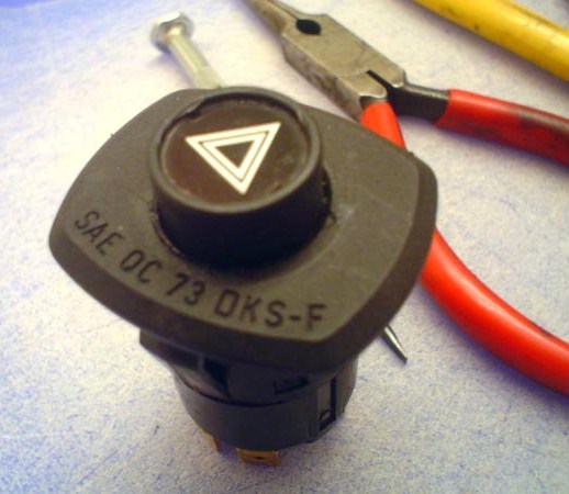
Here's the emergency flasher from my 1980 528i. These seem to fail in every car, sooner or later. The button pops outward and when you push it back in, it doesn't stay. So now your flashers are on all the time. I had one give way at night, so when I went to start the car the next morning, my battery was drained. Pretty annoying!
Here are some basic instructions on how to fix them when the go Ka-Put.
The general anatomy of this switch in this discussion is;
TOOLS REQUIRED will be
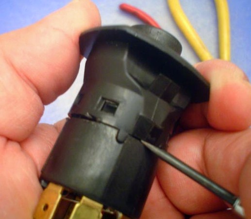
Using the screw driver, work it onto the seam and try to separate the front bezel (face portion) from the switch body.
BE CAREFUL you can easily slip and STAB your hand if you're not accustomed to this operation; Leather gloves might be a good idea about now.

Once the blade of the screwdriver gets a little separation, slip it under the bezel skirt and lift the rectangular holes up and over the body snaps. Work your way around the lap joint CAREFULLY as to not damage the switch and your fingers.

In separating the fore and aft portions, be aware of an internal compression spring that applies opposing force. One end could "JUMP" off as the spring launches it.

In the body there is a claw pin that rides in a latch guide. This claw pin usually gets over stressed and over time, will bend slightly outward. We need to fix this by using the long nose plyers and genltly bent it so the claw pin is a little more inward. (Don't brute-force it too much, the lever could break off at the base). This causes the pin to extend deeper in the guide for more positive engagement.

Here's a close-up of the claw pin as it has been tweaked inward. Note this doesn't need to be very much. Make the pin come inward about 1/32 of an inch (1 mm).
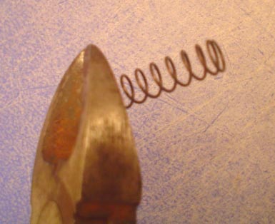
Remove the compression spring and snip off the last coil on one end. Only do this on ONE END. What we are doing here is reducing the total spring force -- the same force that was overloading the claw pin in the first place. A very cool option is to take the spring down to a hardware store that carries a broad selection of little mechanism springs and try to select one that is the same size, but smaller wire diameter; lower spring rate = lower assembled force.

Remove the front bezel from the button. Make a mental note of how the button fits into the forward bezel.

Okay, HERE'S THE TRICKY PART. With the front bezel removed from the button. We need to assemble the button into the rear body and set the claw pin into the pin guide.

Work the buttom body into the rear body such that the claw pin rides up into the guide and back down so it catches. Got that? This is a two-handed operation, I'm using my other hand to operate the camera.

You must get to this point in the assembly where the pin is caught in the guide; the button and rear body are held together with the claw pin.

Slide the bezel over the button and snap the bezel together with the rear body. Keep track of the alignment tongue and groove.

Here's the switch after snapping it together.
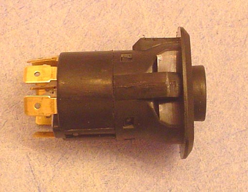
Test the mechanical operation of the switch; push to catch the "IN" position, then push to release to the "OUT" position. Cycle it a few times to make sure it's going to work.
CONGRATULATIONS! Now go re-install it in your car.
Back to Frequently asked questions
© 2010, FirstFives.org™