Updated 4/28/2003
Back to Frequently asked questions
Courtesy of Peter Florance (with help from Mr Coffey, Robert Bondi and Alan Villanova).
Sluggish or non-working electric locks are a common problem with e12's; especially those on the east coast. This FAQ describes how to repair the central locking system and lockmotors themselves, which are expensive and in at least one case no longer available.
If all your locks are sluggish or not working at all, you should check the door latch mechanisms first. By now they are gummy with hardened grease. The lockmotor is not strong enough to overcome the most stubborn latch mechanism so free up the mechanism first. Some brake solvent or WD40 will flush out the old grease. Then relube with spray lithium grease. I'd love to liquify some Redline CV-2 grease and soak the mech in it; but I haven't figured out how to do that yet. The manual lock button should be fairly easy to unlock; you'll feel the difference!
Also check the Central Locking System fuse, as well as the body to battery ground strap. If it's frayed or the metal on the chassis under the strap connection is not bright shiny clean, that can cause the problem. If only one door is affected, it's possible the lockmotor needs repair. I've also seen cases (especially in cars with crank windows) where the harness from the body to the door is broken. The connections of the three wires can be checked with an ohm meter (disconnect battery ground cable first) from the lock motor harness connector in the door to the harness connection in the body (located in speaker holes for front doors, underneath B piller trim (I think) for rear doors.
A diagram of the Central Locking System can be found here (opens in new window). You'll need Adobe Acrobat to view the diagram.
Mr Coffey adds:
"I finally got my central locking system FULLY functional
today. The last problem holding me back was a faulty driver's
door switch. Since it's not really a lock motor and SHOULD NOT be
tested the same way as the others, I thought we could update the
FAQ with a way to determine if everything else is working. (And
thus, the driver's door switch is bad.)
Here's what I did:
Inside the driver's door, I disconnected the switch from the 5
wires at the plugs. One plug has only red/white, the other has
brown, blue, white & red/green.
a) It is my understanding that the red/white wire always be hot
(+).
b) If this is OK, then the lockmotor bench-test
method can be applied to the brown, blue and white wires that
lead to the rest of the system and NOT to the driver's switch. By
using this method, all other locks should operate normally.
If a & b both check out, the driver's switch must be faulty
by process of elimination."
Assuming all above is ok then you can check the motors themselves. Before you start on the lock motors, get replacement clips and grommets for the linkages. They will be brittle and may break while removing the components. The bushing for the lock motor is 51.22.1.817.032 and the lock to linkage rod clipis 52-20-8-238-999 (was 51-21-6-442-159 thanks Robert Bondi).
The lockmotors can be bench-tested with a 12 volt power source. You'll need to attach the brown wire to the - side of the supply. Apply the blue wire to + and the white wire to - will drive the motor in one direction until the limit switches stop it. Reversing blue and white wires (leave brown on -) will drive it the other way.
Click on image for full size
To open the motor, drill out the four rivots shown above. At the bottom of the picture is the linkage which attaches to your door mechanism. Note that these are part of the mounting studs which extend from the other side. Just drill until you clear the rivot and the cases will separate as below:

Click on image for full size
Note the motor under the black case that drives the white threaded rod. The golden colored follower rides back and forth on the threaded rod, from locked to unlocked, pivoting the linkage shaft. The travel of the follow is limited by the two beige colored switches on the right half of the open lock motor (above). Clean these switch contacts (2 sets per switch) with a burnishing tool or 1200 grit sandpaper. Don't file the rounded contacts flat; just knock off any oxidation that's present. Spray some silicone lubricant in the case to repel water. You can lube the screw with high quality grease like Redline CV2.
Put the halves back together with a few thick rubber bands. Then wick some crazy glue in 4-5 short spots around the case and let dry. By just glueing a few spots you'll be able to break it open again if need be. You could also RTV silicone around the edge.
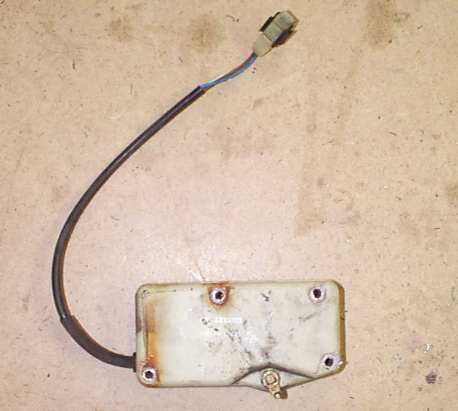
Here's a picture of the driver's door central locking system controller (thanks Sean 'Kaveman' Steinman).

Alan Villanova adds these notes regarding the
controller:
I found my unit was not timing out properly and the relay was
staying energized constantly. There are only two active
components on the board which are two NPN transistors in the
timing circuit. I replaced the transistors and tested the module
and it is working properly. I purchased extra transistors so if
there is anyone that needs to repair their module I can send them
the parts. It does require removing the arm from the post that
activates the switch by grinding off the top where it is staked
onto the shaft so you can remove the lever and then remove the
circuit board so you can replace the transistors. Basic soldering
skills are required. Then use epoxy to refasten the arm onto the
post. Then just follow the FAQ for putting the housing back
together. I thought this information might be useful. The
transistor part numbers are BC547B & BC337 and can be
purchased from Newark Electronics. Also I have repaired my window
motor that was locked up. It's really quite simple. It's a
standard motor set up with fixed magnets, a wound rotor and
carbon brushes. I foundthe motor was not working because the
rotor shaft had rust on the bearing ends. I took all the gearing
out of the motor and removed the rotor. I lightly sanded the rust
off of the shaft and then applied grease. Put the
rotor back into the housing which requires tying the brushes back
with thread and then cutting the thread once the rotor is in
place. I remove all the old grease from the gears and applied new
grease. Put the unit back together and tested the unit. There is
an adjustment screw on the gear end of the rotor shaft to take
out the play. If that's too tight it will bind the motor slightly.
That screw should have moderate torque applied to it. You can
tell by running the motor in both directions to make sure it
sounds like it is not laboring. I will probably take the drivers
side motor out so I can lubricate the rotor bearings on it just
for preventive maintenance. I can take pictures of the motor and
it's components and come up with a step by step procedure for the
repair. Also while the door is apart lubricate the ball bearing
rollers on the window tracks and all the door lock linkage.
(Click for full size image)
Back to Frequently asked questions
© 2002, FirstFives.org™